
Current Issue
The Utilization/Implementation of a Unified Power Flow Controller to Enhance Voltage Stability Within a Heavily Congested Electrical Network
Adebayo Adeniyi D1,Emu chuks2
1Department of Electrical and Electronic Engineering,Federal University Otuoke, 562103, Bayelsa, Nigeria.
2Department of Electrical and Electronic Engineering,Niger Delta University,Amassoma 560103,Nigeria.
1email: adebayoad@fuotuoke.edu.ng,2email: emu.chuks@gmail.com.
----------------------------------------------------------------------------------------------------------------------------------------------------------------------------------------------------------------------------------------------------------------------------
ABSTRACTThe growing intricacies and needs of contemporary power systems often face issues such as voltage instability, line overloads, and power losses, which undermine the reliability and efficiency of electric networks. This study examines the application and execution of a Unified Power Flow Controller (UPFC) as a strong strategy to improve voltage stability and alleviate congestion in overloaded electrical networks. The UPFC, a flexible device classified under Flexible AC Transmission Systems (FACTS), combines series and shunt compensation functions, allowing for dynamic management of power flow, voltage levels, and phase angles on transmission lines. Through analytical modeling, simulations, and case analyses, this research illustrates how utilizing a UPFC can enhance system performance by controlling reactive power, minimizing line overload, and ensuring voltage profiles remain within acceptable limits. The results emphasize the UPFC's capacity to refine power quality, boost system adaptability, and reinforce grid stability in reaction to variable load demands and increasing energy requirements. Suggestions for real-world application, including cost factors and integration hurdles, are also presented to encourage the uptake of this state-of-the-art technology in modern power systems.
Keywords:Contemporary power system, Controlling reactive power, Electric networks, Flexible AC Transmission Systems, Reactive power, Real-world application, Modern power systems, Unified Power Flow Controller.
1. INTRODUCTIONThe rising cost of electricity has become a significant issue for both consumers and electric service providers. Both utility and customer-side disruptions can lead to transients, waveform distortions, and changes in terminal voltage throughout the electrical grid, all of which can lead to power quality problems. Power Quality (PQ), is the term that refers to keeping voltage and current waveforms sinusoidal at their rated frequency and amplitude. Ensuring power quality in power systems has recently become a top priority due to the rise of equipment with power electronic devices, which are more susceptible to power quality issues [1]. The increase in non-linear loads, such as power electronic devices, variable speed drives, and electronic control gears, has a major effect on power quality. Inadequate power quality can affect how safely, dependably, and effectively systems operate. Power quality is defined by elements such as voltage sags, swells, fluctuations, imbalances, and harmonics. By introducing a growing array of technologies that offer more control options for the power system, power electronic devices such as Flexible AC Transmission Systems (FACTS) and custom power tools have opened up new avenues for improving power quality.
The current power infrastructure has been deregulated to allow different organisations to handle generation, transmission, and distribution in an effort to reduce power bills. It is necessary to optimise current generation units, stress transmission lines to their thermal capacity, and maintain system stability as power demand rises. It is also necessary to minimise transmission-line losses. In order to control power flow and increase current-line capacity, FACTS devices are essential. These units improve controllability and power transfer capacity by using power electronic devices. Future gearbox systems may become more intelligent as a result of FACTS technology.
Static Synchronous Compensator (STATCOM), Thyristor Controlled Series Capacitor (TCSC), Static Series Synchronous Compensator (SSSC), and Static VAR Compensator (SVC) are among the devices that falls under the FACTs controllers. In order to promote stability in voltage and improve power quality, FACTs controllers can react swiftly to changes in system conditions. The inability to provide the necessary reactive power requirements, which can happen during faults, overloading, or voltage changes, can upset voltage stability. By supplying or absorbing reactive power to stabilise the system, FACTs equipment can balance variations in reactive power [2].
The Unified Power Flow Controller (UPFC) is the most versatile FACTS technology. Static Synchronous Compensator (STATCOM), Thyristor Switched Capacitor (TSC), Thyristor-Controlled Reactor (TCR), and Phase Angle Regulator are among the devices that UPFC can integrate. Furthermore, UPFC surpasses this by integrating desired features in these gadgets [3]. By connecting voltage in series with transmission lines, UPFC can independently control the phase angle and voltage magnitude, thereby controlling both real power and reactive power flow. In order to achieve full capacity utilisation, this allows power flow management in the desired directions through transmission lines, allowing transmission lines to operate until they reach their thermal limits. Power grids employ UPFCs to further enhance small signal and transient stability [4-35].
2. MATERIALThe objective of this chapter is to analyze the methods of modeling and simulation applied to the power system network, along with the UPFC models that manage the bus voltages within the system. Additionally, it presents a detailed mathematical framework for the solutions implemented in the simulations. The one-line representation of the power system serving as the basis for this project is depicted in the Figure (1) below.
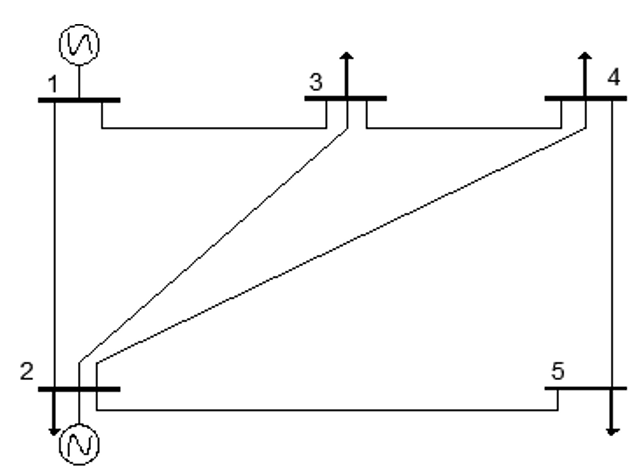
Figure 1: One line diagram of the power system model
To achieve improved voltage stability, proper placement of the UPFC is essential. In order to determine the optimal locations, a load flow analysis identified the system's weak buses. Although there are a number of approaches for examining load flow, the Newton Raphson technique has succeeded in being the most effective because of its robust convergence properties. Thus, the project employed this technique to ascertain the steady-state voltages at each bus in the system.
2.2 Newton Raphson Load Flow MethodThis approach uses iteration to solve the following set of nonlinear algebraic equations as mentioned Equation (1).
Where F represents the set of ‘n’ nonlinear equations, and X is the vector of ‘n’ unknown state variables.
The essence of the method consists of determining the vector of state variables X by performing a Taylor series expansion of F(X) about an initial estimate X (0):
F(X)=F(X((0) ) )+J(X((0) ) )(X-X((0) ) )+Higher-order termswhere J(X (0)), also known as the Jacobian, is a matrix of first-order partial derivatives of F(X) with respect to X, evaluated at X=X (0).
With the assumption that X (1) is the value that the algorithm computes at iteration 1 and that this value is sufficiently close to the initial estimate X (0), this expansion lends itself to a suitable formulation for computing the vector of state variables X. This assumption allows for the neglect of all high-order derivative terms in Equation (2). Therefore
In compact form, and generalizing the above expression for the case of iteration (i),
\[
F\bigl(X^{(i)}\bigr) \approx F\bigl(X^{(i-1)}\bigr) + J\bigl(X^{(i-1)}\bigr)\bigl(X^{(i)} - X^{(i-1)}\bigr)
\]
(3)
Where i = 1, 2 . . . .
Furthermore, if it is assumed that X(i) is sufficiently close to the solution X(*), then FX(i) ≈ FX(*) = 0.
Hence, Equation (3) becomes
\[
F\bigl(X^{(i-1)}\bigr) + J\bigl(X^{(i-1)}\bigr)\bigl(X^{(i)} - X^{(i-1)}\bigr) = 0
\]
(4)
and solving for X(i),
\[X^{(i)} = X^{(i-1)} - J^{-1}\bigl(X^{(i-1)}\bigr)\,F\bigl(X^{(i-1)}\bigr)\]
(5)
The iterative solution can be expressed as a function of the correction vector
ΔX(i)= X(i) - X(i -1),
\[\Delta X^{(i)} = X^{(i)} - X^{(i-1)}\]
(6)
and the initial estimates are updated using the following relation:
\[ X^{(i)} = X^{(i-1)} + \Delta X^{(i)}\]
(7)
We repeat the computations as many times as necessary, using the most recent values of X in Equation (6). This process continues until the mismatches ΔX fall within the specified small tolerance, which is 1e -12.
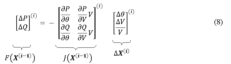
To apply the Newton Raphson approach to the power flow problem, the fundamental equations must be expressed in the form of Equation (9), where X is the set of unknown nodal voltage magnitudes and phase angles. Since the power mismatch equations ΔP and ΔQ are magnified around a base point (θ(0), V(0)), the power flow Newton Raphson algorithm can be explained by the following connection:
The various matrices in the Jacobian may consists of up to (nb - 1) × (nb - 1) elements of the form:
Where k and m are the values of 1 and nb respectively. nb is the number of buses who have had the slack bus entries eliminated. Also eliminated are the PV bus rows and columns that correspond to reactive power and voltage magnitude. Furthermore, when buses k and m are not directly connected by a gearbox element, the corresponding k–m item in the Jacobian is null. Power flow Jacobians are relatively sparse in real power networks due to their relatively low levels of connectivity. One of their characteristics is that they are symmetrical in structure but not in value. Additional To counteract the multiplication of the Jacobian terms (∂PK/∂Vm)Vm and (∂QK/∂Vm)Vm by Vm, the correction terms ΔVm are divided by Vm. The derivative terms given below show how this trick results in useful, simplify able calculations.
Figure 2: A two bus system for illustrating Newton Raphson Power flows
Finding correlations between injected bus currents and bus voltages is essential to creating appropriate power flow equations. The injected complex current at bus k, represented by IK, can be expressed as follows in terms of the complex bus voltages Ek and Em based on Figure 3.2:
\[I_k \;=\; \frac{1}{\mathcal{z}_{km}}(E_k - E_m) \;=\; y_{km}(E_k - E_m)\]
(10)
Similarly for bus m,
\[I_m \;=\; \frac{1}{\mathcal{z}_{mk}}(E_m - E_k) \;=\; y_{mk}(E_m - E_k)\]
\[I_m \;=\; \frac{1}{\mathcal{z}_{mk}}(E_m - E_k) \;=\; y_{mk}(E_m - E_k)\]
(11)
The above equations can be written in matrix form as,
\[\begin{bmatrix}I_k\\[4pt]I_m\end{bmatrix}
=\begin{bmatrix} y_{km} & -y_{km}\\[4pt] -y_{mk} & y_{mm}\end{bmatrix}
\begin{bmatrix}E_k\\[4pt]E_m\end{bmatrix}\]
(12)
\[\begin{bmatrix}I_k\\[4pt]I_m\end{bmatrix}
=\begin{bmatrix} Y_{kk} & Y_{km}\\[4pt] Y_{mk} & Y_{mm}\end{bmatrix}
\begin{bmatrix}E_k\\[4pt]E_m\end{bmatrix}\]
(13)
Where the bus admittances and voltages can be expressed in more explicit form:
\[Y_{ij} = G_{ij} + j\,B_{ij}\]
(14)
\[E_i = V_i e^{j\theta_i} = V_i\bigl(\cos\theta_i + j\sin\theta_i\bigr)\]
(15)
Where i = k, m; j = k, m
The active and reactive components of the complex power injected at bus k can be represented as a
function of the bus's injected current and nodal voltage:
\[S_k = P_k + jQ_k = E_k I_k^{*}\]
(16)
Twhere IK is the complex conjugate of the current injected at bus k.
The expressions for pkcal and Qkcalcan be determined by substituting Equations (4) and (5) into
Equation 16, and separating into real and imaginary parts:
\[
P_k = V_k^{2}G_{kk} + V_k V_m\bigl[G_{km}\cos(\theta_k-\theta_m) + B_{km}\sin(\theta_k-\theta_m)\bigr]
\]
(17)
\[
Q_k = -V_k^{2}B_{kk} + V_k V_m\bigl[G_{km}\sin(\theta_k-\theta_m) - B_{km}\cos(\theta_k-\theta_m)\bigr]
\]
(18)
Equations (17) and (18) are the two important power flow equations and are used in deriving the Jacobian matrix.
2.2.2. Forming The Jacobian MatrixFor k ≠ m,
\[
\frac{\partial P_{k,\ell}}{\partial \theta_{m,\ell}}
= V_k V_m\bigl[G_{km}\sin(\theta_k-\theta_m) - B_{km}\cos(\theta_k-\theta_m)\bigr]
\]
(19)
\[
\frac{\partial P_{k,\ell}}{\partial V_{m,\ell}}V_{m,\ell}
= V_k V_m\bigl[G_{km}\cos(\theta_k-\theta_m) + B_{km}\sin(\theta_k-\theta_m)\bigr]
\]
(20)
\[
\frac{\partial Q_{k,\ell}}{\partial \theta_{m,\ell}}
= -\,\frac{\partial P_{k,\ell}}{\partial V_{m,\ell}}V_{m,\ell}
\]
(21)
\[
\frac{\partial Q_{k,\ell}}{\partial V_{m,\ell}}V_{m,\ell}
= \frac{\partial P_{k,\ell}}{\partial \theta_{m,\ell}}
\]
(22)
For K = m,
\[
\frac{\partial P_{k,\ell}}{\partial \theta_{k,\ell}}
= -\,Q_{k}^{cal} - V_k^{2}B_{kk}
\]
(23)
\[
\frac{\partial P_{k,\ell}}{\partial V_{k,\ell}}V_{k,\ell}
= P_{k}^{cal} + V_k^{2}G_{kk}
\]
(24)
\[
\frac{\partial Q_{k,\ell}}{\partial \theta_{k,\ell}}
= P_{k}^{cal} + V_k^{2}G_{kk}
\]
(25)
Figure 3: Unified power flow controller equivalent circuit
The UPFC’s voltage sources are:
\[
E_{vR} = V_{vR}\bigl(\cos\delta_{vR}+j\sin\delta_{vR}\bigr)
\]
(26)
\[
E_{cR} = V_{cR}\bigl(\cos\delta_{cR}+j\sin\delta_{cR}\bigr)
\]
(27)
where VvRand δvR are the controllable magnitude (VvR min)≤VvR≤V(vR max)) and phase angle (0≤δvR≤ 2π) of the voltage source representing the shunt converter. The magnitude VcR and phase angle δcR of the voltage source representing the series converter are controlled between limits (V(vR min)≤VvR≤V(vR max)) and (0≤δvR≤ 2π), respectively.
TThe phase angle of the series-injected voltage determines the mode of power flow control. If δcR The UPFC controls the terminal voltage when it is in phase with the nodal voltage angle θk. As a phase shifter, δcR regulates active power flow when it is in quadature with respect to θk. As a variable series compensator, δcR regulates active power flow if it is in quadrature with the line current angle. The UPFC functions as a voltage regulator, variable series compensator, and phase shifter at all other values of δcR. Controlling the amount of power flow depends on the magnitude of the series-injected voltage.
Based on the equivalent circuit shown in Figure (3) and Equations (26) and (27), the active and reactive power equations at bus k are:
\[
\begin{aligned}
P_k &= V_k^{2}G_{kk}
+ V_k V_m\bigl[G_{km}\cos(\theta_k-\theta_m)+B_{km}\sin(\theta_k-\theta_m)\bigr] \\[6pt]
&\quad + V_k V_{cR}\bigl[G_{km}\cos(\theta_k-\theta_{cR})+B_{km}\sin(\theta_k-\theta_{cR})\bigr] \\[6pt]
&\quad + V_k V_{vR}\bigl[G_{vR}\cos(\theta_k-\theta_{vR})+B_{vR}\sin(\theta_k-\theta_{vR})\bigr]
\end{aligned}
\]
(28)
\[
\begin{aligned}
Q_k &= -V_k^{2}B_{kk}
+ V_k V_m\bigl[G_{km}\sin(\theta_k-\theta_m)-B_{km}\cos(\theta_k-\theta_m)\bigr] \\[6pt]
&\quad + V_k V_{cR}\bigl[G_{km}\sin(\theta_k-\delta_{cR})-B_{km}\cos(\theta_k-\delta_{cR})\bigr] \\[6pt]
&\quad + V_k V_{vR}\bigl[G_{vR}\sin(\theta_k-\delta_{vR})-B_{vR}\cos(\theta_k-\delta_{vR})\bigr]
\end{aligned}
\]
(29)
\[
P_m = V_m^{2}G_{mm} + V_m V_k\bigl[G_{mk}\cos(\theta_m-\theta_k)+B_{mk}\sin(\theta_m-\theta_k)\bigr]
+ V_m V_{cR}\bigl[G_{mm}\cos(\theta_m-\delta_{cR})+B_{mm}\sin(\theta_m-\delta_{cR})\bigr]
\]
(30)
\[
Q_m = -V_m^{2}B_{mm} + V_m V_k\bigl[G_{mk}\sin(\theta_m-\theta_k)-B_{mk}\cos(\theta_m-\theta_k)\bigr]
+ V_m V_{cR}\bigl[G_{mm}\sin(\theta_m-\delta_{cR})-B_{mm}\cos(\theta_m-\delta_{cR})\bigr]
\]
(31)
Series converter:
\[
\begin{aligned}
P_{cR} &= V_{cR}^{2} G_{mm}
+ V_{cR} V_k\bigl[G_{km}\cos(\delta_{cR}-\theta_k)+B_{km}\sin(\delta_{cR}-\theta_k)\bigr] \\[6pt]
&\quad + V_{cR} V_m\bigl[G_{mm}\cos(\delta_{cR}-\theta_m)+B_{mm}\sin(\delta_{cR}-\theta_m)\bigr]
\end{aligned}
\]
(32)
\[
\begin{aligned}
Q_{cR} &= -V_{cR}^{2} B_{mm}
+ V_{cR} V_k\bigl[G_{km}\sin(\delta_{cR}-\theta_k)-B_{km}\cos(\delta_{cR}-\theta_k)\bigr] \\[6pt]
&\quad + V_{cR} V_m\bigl[G_{mm}\sin(\delta_{cR}-\theta_m)-B_{mm}\cos(\delta_{cR}-\theta_m)\bigr]
\end{aligned}
\]
(33)
Shunt converter:
\[
P_{vR} = -V_{vR}^{2} G_{vR} + V_{vR} V_k\bigl[G_{vR}\cos(\delta_{vR}-\theta_k) + B_{vR}\sin(\delta_{vR}-\theta_k)\bigr]
\]
(34)
\[
Q_{vR} = V_{vR}^{2} B_{vR} + V_{vR} V_k\bigl[G_{vR}\sin(\delta_{vR}-\theta_k) - B_{vR}\cos(\delta_{vR}-\theta_k)\bigr]
\]
(35)
Under the assumption of lossless converter valves, the active power required by the series converter and the active power supplied to the shunt converter, PvR, are equal, PcR; that is,
\[
P_{vR} + P_{cR} = 0
\]
(36)
Assuming that there is no resistance in the coupling transformers, the active power at bus k is equal to the active power at bus m. Consequently,
\[
P_{vR} + P_{cR} = P_k + P_m = 0
\]
(37)
SIt combines the AC network power equations with the linearised UPFC power equations. In the event that the following parameters are under UPFC control: Assuming that bus m is a PQ bus, the linearised system of equations is as follows: (1) voltage magnitude at the shunt converter terminal (bus k); (2) active power flow from bus m to bus k; and (3) reactive power injected at bus m.
\[
\begin{bmatrix}
\Delta P_k\\[4pt]
\Delta P_m\\[4pt]
\Delta Q_k\\[4pt]
\Delta Q_m\\[4pt]
\Delta P_{mk}\\[4pt]
\Delta Q_{mk}\\[4pt]
\Delta P_{bb}
\end{bmatrix}
=
\begin{bmatrix}
\dfrac{\partial P_k}{\partial \theta_k} & \dfrac{\partial P_k}{\partial \theta_m} & \dfrac{\partial P_k}{\partial V_{vR}}V_{vR} & \dfrac{\partial P_k}{\partial V_m}V_m & \dfrac{\partial P_k}{\partial \delta_{cR}} & \dfrac{\partial P_k}{\partial V_{cR}}V_{cR} & \dfrac{\partial P_k}{\partial \delta_{vR}}\\[10pt]
\dfrac{\partial P_m}{\partial \theta_k} & \dfrac{\partial P_m}{\partial \theta_m} & 0 & \dfrac{\partial P_m}{\partial V_m}V_m & \dfrac{\partial P_m}{\partial \delta_{cR}} & \dfrac{\partial P_m}{\partial V_{cR}}V_{cR} & 0\\[8pt]
\dfrac{\partial Q_k}{\partial \theta_k} & \dfrac{\partial Q_k}{\partial \theta_m} & \dfrac{\partial Q_k}{\partial V_{vR}}V_{vR} & \dfrac{\partial Q_k}{\partial V_m}V_m & \dfrac{\partial Q_k}{\partial \delta_{cR}} & \dfrac{\partial Q_k}{\partial V_{cR}}V_{cR} & \dfrac{\partial Q_k}{\partial \delta_{vR}}\\[8pt]
\dfrac{\partial Q_m}{\partial \theta_k} & \dfrac{\partial Q_m}{\partial \theta_m} & 0 & \dfrac{\partial Q_m}{\partial V_m}V_m & \dfrac{\partial Q_m}{\partial \delta_{cR}} & \dfrac{\partial Q_m}{\partial V_{cR}}V_{cR} & 0\\[8pt]
\dfrac{\partial P_{mk}}{\partial \theta_k} & \dfrac{\partial P_{mk}}{\partial \theta_m} & 0 & \dfrac{\partial P_{mk}}{\partial V_m}V_m & \dfrac{\partial P_{mk}}{\partial \delta_{cR}} & \dfrac{\partial P_{mk}}{\partial V_{cR}}V_{cR} & 0\\[8pt]
\dfrac{\partial Q_{mk}}{\partial \theta_k} & \dfrac{\partial Q_{mk}}{\partial \theta_m} & 0 & \dfrac{\partial Q_{mk}}{\partial V_m}V_m & \dfrac{\partial Q_{mk}}{\partial \delta_{cR}} & \dfrac{\partial Q_{mk}}{\partial V_{cR}}V_{cR} & 0\\[8pt]
\dfrac{\partial P_{bb}}{\partial \theta_k} & \dfrac{\partial P_{bb}}{\partial \theta_m} & \dfrac{\partial P_{bb}}{\partial V_{vR}}V_{vR} & \dfrac{\partial P_{bb}}{\partial V_m}V_m & \dfrac{\partial P_{bb}}{\partial \delta_{cR}} & \dfrac{\partial P_{bb}}{\partial V_{cR}}V_{cR} & \dfrac{\partial P_{bb}}{\partial \delta_{vR}}
\end{bmatrix}
\begin{bmatrix}
\Delta \theta_k\\[6pt]
\Delta \theta_m\\[6pt]
\Delta V_{vR}/V_{vR}\\[6pt]
\Delta V_m/V_m\\[6pt]
\Delta \delta_{cR}\\[6pt]
\Delta V_{cR}/V_{cR}\\[6pt]
\Delta \delta_{vR}
\end{bmatrix}
\]
(38)
The MATLAB script implementing the above Newton-Raphson load flow and the incorporation of the UPLC equations is given in appendix A
3. RESULTS ANALYSISThis section showcases the findings derived from the simulations and evaluates them according to the project's defined goals.
3.1 CASE 1:The Newton-Raphson load flow has been conducted without the UPFC, treated as the standard condition. The outcomes are illustrated in tables (1) and (2).
Table 1: Bus Voltages Without the UPFC
| Bus | Voltage (p.u.) | Voltage Angle (degree) |
|---|---|---|
| 1 | 1.0600 | 0.0000 |
| 2 | 1.0000 | -2.0612 |
| 3 | 0.9872 | -4.6367 |
| 4 | 0.9841 | -4.9570 |
| 5 | 0.9717 | -5.7649 |
Figure 4: voltages of the buses without the UPFC between buses 3 and 4
###############################################################################

                               Line Flow and Losses
-------------------------------------------------------------------------------

|From|To  |   P    |   Q     | From | To |    P     |    Q     | Line Loss    |
|Bus |Bus |   MW   |  MVar   | Bus  |Bus |    MW    |   MVar   |   MW    MVar |
-------------------------------------------------------------------------------
  1    2    89.331   73.995     2     1    -86.846   -72.908     2.486   1.087
-------------------------------------------------------------------------------
  1    3    41.791   16.820     3     1    -40.273   -17.513     1.518  -0.692
-------------------------------------------------------------------------------
  2    3    24.473   -2.518     3     2    -24.113    -0.352     0.360  -2.871
-------------------------------------------------------------------------------
  2    4    27.713   -1.724     4     2    -27.252    -0.831     0.461  -2.554
-------------------------------------------------------------------------------
  2    5    54.660    5.558     5     2    -53.445    -4.829     1.215   0.729
-------------------------------------------------------------------------------
  3    4    19.386    2.865     4     3    -19.346    -4.688     0.040  -1.823
-------------------------------------------------------------------------------
  4    5     6.598    0.518     5     4     -6.555    -5.171     0.043  -4.652
-------------------------------------------------------------------------------

                               Total Loss          6.122  -10.777

###############################################################################
Newton-Raphson load flow carried out with the UPFC incorporated between buses 3 and 4 to control nodal voltage and increase active power flows. This result is depicted in tables (3) and (4)
Table 3. Bus Voltages With UPFC
| Bus | Voltage (p.u.) | Voltage Angle (degree) |
|---|---|---|
| 1 | 1.0600 | 0.0000 |
| 2 | 1.0000 | -1.7693 |
| 3 | 1.0000 | -6.0161 |
| 4 | 0.9971 | -3.1906 |
| 5 | 0.9745 | -4.9741 |
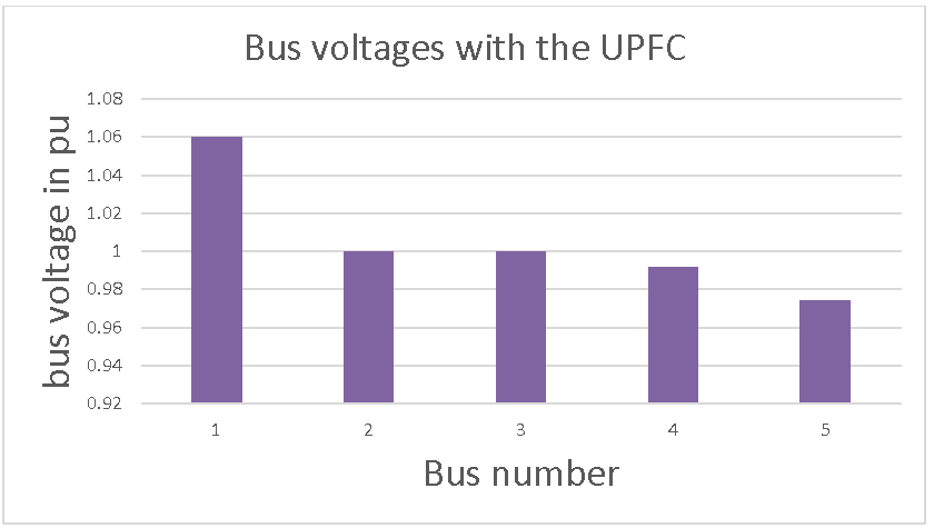
Figure 5: Voltages of the buses with the UPFC between buses 3 and 4
Table 4. Line Flows and Losses With UPFC
###############################################################################

                               Line Flow and Losses
-------------------------------------------------------------------------------

|From|To  |   P    |   Q     | From | To |    P     |    Q     | Line Loss    |
|Bus |Bus |   MW   |  MVar   | Bus  |Bus |    MW    |   MVar   |   MW    MVar |
-------------------------------------------------------------------------------
  1    2    81.143   76.424     2     1    -78.838   -75.879     2.305   0.545
-------------------------------------------------------------------------------
  1    3    50.341    9.343     3     1    -48.431    -8.924     1.909   0.419
-------------------------------------------------------------------------------
  2    3    37.484   -12.969    3     2    -36.569    11.715     0.915  -1.254
-------------------------------------------------------------------------------
  2    4    13.739    -1.780    4     2    -13.626    -1.847     0.113  -3.627
-------------------------------------------------------------------------------
  2    5    47.614     5.140    5     2    -46.690    -5.291     0.924  -0.151
-------------------------------------------------------------------------------
  3    4    40.000     2.000    4     3    -39.838    -3.490     0.162  -1.490
-------------------------------------------------------------------------------
  4    5    13.464     0.337    5     4    -13.310    -4.709     0.154  -4.371
-------------------------------------------------------------------------------

                               Total Loss          6.484   -9.929

###############################################################################
The energy flows in the network enhanced by the UPFC are unlike the initial conditions, which was anticipated. The most noticeable changes are that bus 3 experiences an increase of 20% and 53% in active power supplied by generator buses 1 and 2, respectively. This increase stems from the significant active power demands of the UPFC series converter. The strength of the UPFC shunt bus will influence the highest quantity of active power exchanged between the UPFC and the AC system at bus 3. The generator at bus 1 decreases its reactive power output by approximately 5.6% due to the UPFC generating its own reactive power, while the generator at bus 2 raises its reactive power intake by about 22.6%. Furthermore, the voltage magnitude at bus 3 is kept stable at 1p.u. by the UPFC shunt converter. It is crucial to note that the UPFC maintains active and reactive powers at 40MW and 2MVAR, respectively, as they proceed from the UPFC to bus 3.
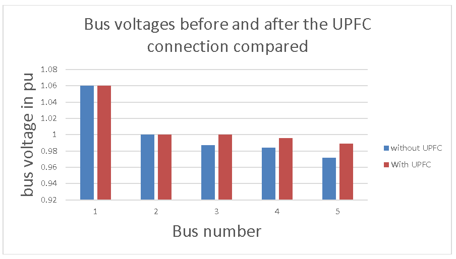
Figure 6: voltages of the buses with and without the UPFC between buses 3 and 4>
Table 5: Bus Data: IEEE 5 Bus System
| Bus No. | Bus Code | Voltage Magnitude | Angle | Load (MW) | Load (MVAR) | Gen (MW) | Gen (MVAR) | Qmin | Qmax |
|---|---|---|---|---|---|---|---|---|---|
| 1 | 1 | 1.06 | 0 | 0.0 | 0.0 | 0.0 | 0.0 | -500 | 500 |
| 2 | 2 | 1 | 0 | 20.0 | 10.0 | 40.0 | 0.0 | -300 | 300 |
| 3 | 3 | 1 | 0 | 46.0 | 16.0 | 0.0 | 0.0 | 0 | 0 |
| 4 | 3 | 1 | 0 | 40.0 | 6.0 | 0.0 | 0.0 | 0 | 0 |
| 5 | 3 | 1 | 0 | 60.0 | 10.0 | 0.0 | 0.0 | 0 | 0 |
Table 6: Line Data for IEEE 5 Bus
| From Bus | To Bus | R | X | B |
|---|---|---|---|---|
| 1 | 2 | 0.02 | 0.06 | 0.06 |
| 1 | 3 | 0.08 | 0.24 | 0.05 |
| 2 | 3 | 0.06 | 0.18 | 0.04 |
| 2 | 4 | 0.06 | 0.18 | 0.04 |
| 2 | 5 | 0.04 | 0.12 | 0.03 |
| 3 | 4 | 0.01 | 0.03 | 0.02 |
| 3 | 5 | 0.08 | 0.24 | 0.05 |
4. CONCLUSION AND RECOMMENDATIONS
4.1 Conclusion
Both active power, measured in watts, and reactive power, measured in volt-amperes reactive or var, are generated and utilized by elements within alternating current systems. Active power is responsible for performing tasks like running motors and illuminating lights. Reactive power plays a crucial role in regulating voltages necessary for maintaining system stability. By managing the generation, absorption, and distribution of reactive power across the network, the voltage profile can be enhanced. Reducing reactive power flows helps in preventing system losses.
>A power flow solution represents a network analysis under steady-state conditions, adhering to specific constraints that dictate system behavior. This solution indicates the nodal voltages, phase angles, and power transfers, given a set of power inputs at each bus and predetermined voltages. Management of reactive power generation, absorption, and overall flow aids in achieving voltage regulation. Sources and sinks of reactive power include rotating synchronous condensers, shunt capacitors, shunt reactors, UPFCs, and various FACTS devices. UPFCs are versatile instruments that utilize power electronic switching elements to regulate nearly all variables controllable within a power system.
This project focused on reactive power compensation and the application of UPFCs to enhance active power transmission in transmission lines. The Newton-Raphson method for power flow analysis was employed to address the flow issue. A modified UPLC power flow model was utilized to evaluate the implications of UPFC on the power system. The altered load flow software was applied to assess the UPFC's impact, installing UPLC between buses 3 and 4.
The simulation was executed using MATLAB. Graphs illustrate the outcomes of a load flow assessment performed on a five-bus system, indicating an improvement in the system's voltage profile. It also became evident that the UPFC was located at a bus where the voltage magnitude was maintained at one p.u.
Based on the analysis, it can be concluded that the UPFC significantly impacts voltage compensation, with power flows directed more towards the nearest bus to it and diminishing as the distance from the bus increases.
4.2 RecommendationsThe conclusion of one research initiative opens doors to possibilities in many related disciplines. The following potential areas for future exploration have been recognized throughout this study:
- An expanded interconnected electrical network, like the IEEE 14, IEEE 30 bus, or larger configurations such as the IEEE 118 bus, could be utilized for load flow analysis.
- In addition to UPFC, other FACTS controllers such as IPFC and STATCOM can be integrated for comparative analysis of their impacts on system performance. Fuzzy logic alongside genetic algorithms may assist in identifying the optimal placement of the UPFC.
- A financial assessment of FACTS technology in comparison to other methods can be conducted.
- S. Asha Kiranmai, M. Manjula and V.R.S. Sarma, “Mitigation of Various Power Quality Problems Using Unified Series Shunt Compensator in PSCAD/EMTDC,” 16th National Power Systems Conference, 15th-17th Dec. 2010.
- D. Mohanty, A, Ahamad, and M. A Khan, “Modeling, Simulation and Performance Analysis of FACTS Controller in Transmission line,” International Journal of Emerging Technology and Advanced Engineering, Vol. 3, No. 5, pp. 429-435, May. 2013.
- V. Mathad, F. R. Basanagouda, and S. H. Jangamshetti, “Voltage Control and Power System Stability Enhancement using UPFC,” International Conference on Renewable Energies and Power Quality (ICREPQ’14), Apr. 2014, Vol.1, No.12, pp. 871-875.
- S. S. Khonde, S. S. Dhamse, and A. G Thosar, “Power Quality Enhancement of Standard IEEE 14 Bus System using Unified Power Flow Controller,” International Journal of Engineering Science and Innovative Technology (IJESIT), Vol. 3, No. 5, pp. 323-334, Sept. 2014.
- L. Gyugyi& Fellow, “Dynamic Compensation of Ac Transmission Lines by Solid-State Synchronous Voltage Sources,” IEEE Transactions on Power Delivery, Vol. 9, No. 2, pp. 904- 911, Apr. 1994.
- L. Gyqyi, T. R. Rietman, A. Edris, C. D. Schauda, s. L .Willirms, and , D.R. Torgerson, “The Unified Power Flow Controller: A New Approach to Power Transmission Control,” IEEE Transactions on Power Delivery, Vol. 10, No. 2, pp. 1085-1097, Apr. 1995.
- Q. Yu, S. D. Round, L. E. Norum, and T. M. Undeland, “Dynamic Control of a Unified Power Flow Controller,” IEEE, pp. 508-514, 1996.
- M. Noroozian, L, Angquist, M. Ghandhari and G. Anderson, “Use of UPFC for Optimal Power Flow Control,” IEEE Transactions on Power Delivery, Vol. 12, No. 4, pp.1629-1634, Oct. 1997.
- Z. Huang, Y. Ni, C. M. Shen, F. W. Felix, S. Chen and B. Zhang, “Application of Unified Power Flow Controller in Interconnected Power Systems—Modeling, Interface, Control Strategy, and Case Study,” IEEE Transactions on Power systems, Vol. 15, No. 2, pp. 817- 824, May. 2000.
- S. Muthukrishnan and A. Kumar, “Comparison of Simulation and Experimental Results of UPFC used for Power Quality Improvement,” International Journal of Computer and Electrical Engineering, Vol. 2, No. 3, pp. 555-559, June. 2010.
- S. Muthukrishnan and A. Kumar, “Enhancement of power Quality in 14 Bus System Using UPFC,” Research journal of Applied Sciences, Engineering and technology,” ISSN. 2040-7467, pp. 356-361, July. 2010.
- D. Murali, M. Rajaram and N. Reka, “Comparison of FACTS Devices for Power System Stability Enhancement,” International Journal of Computer Applications, Vol.8, No.4, pp.30-35, Oct. 2010.
- A.R. Bhowmik and C. Nandi, “Implementation of Unified Power Flow Controller (UPFC) for Power Quality Improvement in IEEE 14-Bus System,” Arup RatanBhowmik et al, Int. J. Comp. Tech. Appl., Vol. 2 (6),1889-1896, 2011.
- Rai, “Enhancement of Voltage Stability & reactive Power Control of Distribution System Using Facts Devices,” International Journal of Scientific Research Engineering & Technology, Vol.1, No. 9, pp. 001-005, Dec. 2012.
- M R. S. Reddy and M. V. Kumar, “Power Quality Improvement in DFIG based Wind Energy Conversion System using UPFC,” IOSR Journal of Engineering (IOSRJEN) Vol. 3, No. 1, pp. 46-54, Jan. 2013.
- K. Gaurav and N. Saxena, “Power Quality improvement using UPFC,” International Journal of Electrical, Electronics and Computer Engineering , Vol.2, No.2, pp. 30- 33, 2013.
- S. Vaibhav Kale, R. P.Prashant and R. Khatri, “Unified Power Flow Controller for Power Quality Improvement,” International Journal of Emerging Science and Engineering (IJESE), Vol.1, No. 10, pp. 1-4, Aug. 2013.
- K. Ravichandrudu, P. S. Pramod Kumar, and, V.E. Sowjanya, “Mitigation of Harmonics and Power Quality Improvement For Grid Connected System Using UPFC,” International Journal of Application or Innovation in Engineering & Management (IJAIEM), Vol. 2, No. 10, pp. 141-156 Oct. 2013.
- Gopinath, N. Vinothini, and S. Kumar, “Modeling of UPFC Using Model Predictive Control and Bacterial Foraging Algorithm,” International Journal of Innovative Research in Computer and Communication Engineering, Vol. 2, No. 1, pp. 2724-2731, Jan. 2014.
- K. S. Lakshmi, G. Sravanthi, L. Ramadevi, and K. H. Chowdary, “Power quality and stability improvement of HVDC transmission System using UPFC for Different uncertainty conditions,” International Journal of Scientific & Engineering Research, Vol. 6, No. 2, pp. 795-801, Feb. 2015.
- M. S. Soruban, J D. Sathyaraj, and J. J. GnanaChandran, “Power Quality Enhancement Using UPFC as an Active Power Filter for Renewable Power Generation,” International Journal of Advanced Research in Electrical, Electronics and Instrumentation Engineering Vol. 4, No. 3, pp. 1712-1718, March. 2015.
- G. Srinivas and T. Santosh Chaitanya, “Enhancement of Power Quality Using FACTS Devices (D-STATCOM),” International Journal of Advanced Research in Electrical, Electronics and Instrumentation Engineering, Vol. 4, No. 4, pp. 1956-1965, Apr. 2015
- P. Kundur Power System stability and control McGraw-Hill, New York (2012)
- Anderson, P. M., & Fouad, A. A. (2008). Power System Control and Stability. Wiley-IEEE Press.
- X. Jiang, J. H. Chow, A.-A. Edris, B. Fardanesh, and E. Uzunovic, “Transfer path stability enhancement by voltage-sourced converter-based FACTS controllers,” IEEE Transactions on Power Delivery, vol. 25, pp. 1019-1025, Apr. 2010.
- L. G. c. E.-H. Narain G. Hingorani, consulting editor., Understanding FACTS : concepts and technology of flexible AC transmission systems New York : IEEE Press 2000
- P. Therond, P. Cholley, D. Daniel, E. Joncquel, L. Lafon, and C. Poumarede, "FACTS research and development program at EDF," in Flexible AC Transmission Systems (FACTS) - The Key to Increased Utilisation of Power Systems, IEE Colloquium on (Digest No.1994/005), 1994, pp. 6/1-615.
- X.-P. Zhang, C. Rehtanz, and B. Pal, "FACTS-Devices and Applications," in Flexible AC Transmission Systems: Modelling and Control, ed: Springer, 2012, pp. 1-30
- J. A. Suul, M. Molinas, and T. Undeland, "STATCOM-Based Indirect Torque Control of Induction Machines During Voltage Recovery After Grid Faults," Power Electronics, IEEE Transactions on, vol. 25, pp. 1240-1250, 2010.
- Thyristor-Controlled Series Capacitors for Power System Compensation," IEEE Transactions on Power Delivery, 2004.
- Sindekar, A &Parate, J. (2012). Reactive Power Control and Transmission loss reduction with realization of SVC and TCSC. (Electronic version). International Journal of Engineering Science and Technology. 4 (7), 3592 – 3600
- Singh, B. etal. (2010). Incorporation of FACTS Controllers in Newton Raphson Load Flow for Power Flow Operation, Control and Planning: A Comprehensive Survey. (Electronic version). International Journal on Computer Science and . 2 (6), 2117- 2124
- Youtube Video: Design and Analysis of UPFC to Improve Power Capacity: Technical University.
- Youtube Video: Lecture on Analysis pf Unified Power Controller: Technical University.
- Enrique, Aetal. (2004). FACTS Modelling and Simulation in Power Networks. India: Thomson Press Ltd, New Delhi.
Authors

Dr. Adebayo D. Adeniyi is a distinguished academic and engineer specializing in Power Systems Engineering, Optimization of Energy Generation, and Electrical Machines. He holds a Bachelor's degree in Electrical and Electronic Engineering from the University of Port Harcourt, Rivers State, as well as a Master's degree in Power Systems and Electrical Machines. His academic journey culminated in a Doctor of Philosophy in Power Systems Engineering from Niger Delta University, Wilberforce Island, Bayelsa State. As a member of the Nigerian Society of Engineers and a chartered Electrical Engineer with the Council for Regulation of Engineering in Nigeria, Dr. Adeniyi has demonstrated his commitment to professional excellence. Currently, he serves as a faculty member at the Federal University Otuoke, Bayelsa State, Nigeria, where he shares his knowledge and expertise with students. With over 35 published peer-reviewed journal articles in both local and international publications, Dr. Adeniyi's research has made significant contributions to his field. His areas of specialization include: - Power Systems Engineering, Optimization of Energy Generation, Electrical Machines. Through his research, teaching, and professional affiliations, Dr. Adeniyi continues to advance the field of Power Systems Engineering and inspire future generations of engineers.

Emu Chuks is a highly skilled Electrical Engineer with a strong academic background and extensive industry experience. He holds a Bachelor's degree in Electrical and Electronic Engineering from the University of Benin, Edo State. He furthered his education by earning a Master's degree in Power Systems and Electrical Machines from the University of Port Harcourt, Rivers State. Currently, Emu is pursuing his Ph.D. in Electrical Power Systems Engineering at Niger Delta University, demonstrating his commitment to advancing his knowledge and expertise in the field. As a registered Electrical Engineer with the Council for Regulation of Engineering in Nigeria (COREN), he has demonstrated his professionalism and adherence to industry standards. With over 10 years of industrial experience, Emu has developed a unique blend of theoretical knowledge and practical expertise, enabling him to effectively navigate complex engineering challenges and contribute to the development of the field. His experience and expertise make him a valuable asset to any organization.