
Current Issue
An Efficient VLSI Architecture for Bi-Cubic Interpolation using Carry Skip Adder
Rao. C. R
Department of Electrical Engineering, Maulana Abul Kalam Azad university of Technology, Kolkata, West Bengal, India
Mandal S. KDepartment of Electrical Engineering, National Institute of Technical Teachers' Training & Research (NITTTR), Kolkata, West Bengal, India.
ABSTRACTIn any signal processing system, signal distortion can occur. A compensation scheme would adjust the captured signal to correct for any deviations and ensure accurate signal transmission and preservation. A compensation scheme is used to correct such deviations for mostly linear is used to enhance the quality of reconstructed signal suitable for high-quality super-resolution techniques. This technique is applicable for multidimensional signal processing such as image processing. Except for the resolution of the acquired images, the extracting of colour information is greatly affected by the number of pixels. This scheme enhances the correlation of interpolated pixels and their immediate neighbouring pixels. This research aims to develop a super-resolution demosaicking (SRD) technique to reconstruct high-resolution, full-colour images from samples of the same previously seen (in-painted) image without a sophisticated, time-consuming training process. Hardware-oriented colour demosaicking methods, which give importance to green colour pixels, have thus enhanced the quality of the restored image. A Boundary Mirror and Detector mechanism also considered here for improving the pixel quality up to the boundaries. Three interpolators were economized by using a method called hardware sharing. The present Bi-Cubic interpolation technique has been designed as part of our overall effort to enhance and advance the SRD approach toward better performance and broader acceptance. This had been implemented by VLSI architecture and VHDL, whereas MATLAB had executed the image conversion and de-conversion methods. Comparison in the evaluation of results was done based on PSNR and SSIM values, followed by the analysis of the output results after the synthesis process using a Xilinx Vivado ZYNQ-7-ZC702 FPGA.
Keywords:Signal processing system, Signal distortion, correlation, Interpolation, Demosaicking, Bi-Cubic interpolation, Colour Images, Super resolution, VLSI architecture, VHDL, MATLAB, PSNR and SSIM.
1. INTRODUCTIONImage interpolation enhances the resolution of an image by filling in the missing details between pixels, thereby converting the given image to high resolution from low resolution one. This process involves creating a high-resolution (HR) image from a similar but lower-resolution version. In digital camera technology, due to limitations, a sample of color is used to represent the pure channel. This technology finds application in various fields, notably portable consumer electronics such as smartphones, tablets, digital video recorders, cameras, and notebooks.
Interpolation is a method of bridging gaps between pixels of similar color to complete a set. However, it often poses challenges related to edge quality and interpolation artifacts. In recent years, various interpolation methods have been employed in demosaicking techniques, such as bilinear interpolation, constant-hue-based interpolation, and gradient-based interpolation etc.. While these methods interpolate between data points, they frequently produce colour artifacts requiring correction.
Demosaicking of mosaic images involves spatial and spectral correlation interpolation, followed by adaptive median filtering to minimize interpolation artifacts in the final full-colour image. Fine-tuning of pixel estimation is performed by considering differences between observed and interpolated images. The estimated full-colour image is converted back to its original colour space, first in the luminance/chrominance colour space, and then smoothed.
Demosaicking, along with denoising, constitutes one of the critical initial processes for rendering high-quality RGB images. A logistic function is introduced to guide demosaicking direction changes without costly edge sensing. This highly parallelizable algorithm, based on the Hamilton–Adams method, is efficiently implemented using FPGAs (Field Programmable Gate Arrays) and GPUs (Graphics Processing Units).
To reduce computational complexity and memory requirements during demosaicking, an end-to-end trained framework incorporates an input data correction process, allowing the network to bypass initial interpolation. Additionally, densely connected residual networks and self-ensemble techniques have been proposed to enhance demosaicking performance without further training or processing.
Hardware-oriented demosaicking algorithms aim to reduce chip area consumption by combining color filter array and bicubic super-resolution demosaicking methods. Recent approaches focus on space reduction through arithmetic operations, utilizing hardware sharing machines for addition, shift, and subtraction processes. Carry-skip adders, instead of traditional full adders, are employed for high-speed and efficient addition procedures.
In conclusion, while learning-based methods are computationally complex and energy-inefficient, the proposed super-resolution demosaicking technique, combined with bicubic interpolation, offers a promising approach to enhancing image quality. The utilization of carry-skip adders and hardware optimization strategies contributes to space, latency, and power efficiency.
2. IMPLEMENTATION OF COLOR DEMOSAICKING ALGORITHM WITH CARRY SKIP ADDER
The proposed methodology introduces a novel linear deviation approach for colour demosaicking. This approach enhances the interpolation process by leveraging green interpolation and a BD (boundary detector) that employs a BMM (boundary mirror machine). The comprehensive colour demosaicking method is illustrated in the block diagram shown in Figure 1. Here’s a detailed explanation of the process:
- 1. Input: The process begins with the input of the Colour Filter Array (CFA) pixel data.
- 2. Boundary Detection: The CFA pixel data is first sent to the boundary detector. This step is crucial for identifying the edges and boundaries within the image, which are essential for accurate interpolation.
- 3. Boundary Mirror Machine: Following boundary detection, the data is processed by the boundary mirror machine. This component effectively mirrors the boundary information to ensure that edge details are preserved during interpolation.
- 4. Linear Deviation Compensation: Using the information from the boundary mirror machine, the system applies a linear deviation compensation technique. This method adjusts the interpolation process to account for deviations, leading to more accurate colour reconstruction.
- 5. Green Interpolation (G'): The technique separates the interpolation process for different colours. For the green channel, denoted as G', only green interpolation is performed. This step ensures that the green colour, which is typically more prevalent and important for human vision, is accurately reconstructed.
- 6. Red-Blue Interpolation (RB'): For the red and blue channels, combined as RB', the interpolation includes both colours. The output of the mirror pixel is integrated into the red and blue interpolation, ensuring that the colour information is accurately maintained across the image.
The proposed method aims to deliver rapid and accurate colour demosaicking by combining these innovative techniques, ensuring high-quality image reconstruction with preserved edge details and minimized colour artifacts.
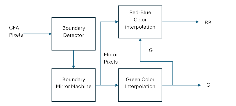
Figure 1 : Block diagram of Color Demosaicking using Red-Blue, Green Interpolation
Figure 2 depicts the color demosaicking design that has been suggested for the VLSI architecture. The input for this design comes from the Buffer Memory at 19660x8, and the value of the memory will be determined using input image processed by MATLAB. The input dimensions of 256 × 256 will be imported into the MATLAB GUI in the first phase; this will facilitate the image's conversion to Hex format, these hexadecimal values will be stored into memory, and in accordance with the image size of 256 x 256, the total number of pixels will be calculated as 65536, and that number will be multiplied by 3. In addition, each pixel has three values, which are denoted by the colors red, green, and blue. Finally, 196608 bits wide are used for the input and output buffer memory. The behavior of each and every pixel will be determined by the next priority block of the control buffer.
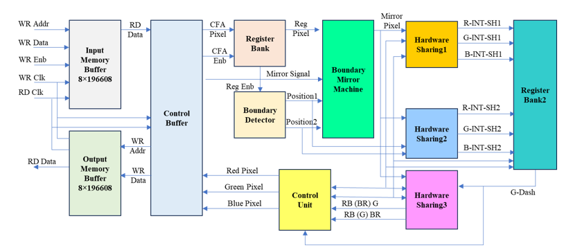
Figure 2 : Top module architecture of Color Demosaicking using Carry Skip Adder
It does this by reading the value from the input buffer memory according to the address increment and then distributing that value to other blocks such as the CU (control unit), RB(register bank) 1, the BD, BMM, and the RB2 along with the HS (hardware sharing) 1, HS2, and hardware sharing 3. The use of a shifter, as opposed to multipliers and divisions, results in a significant reduction in the cost of the necessary hardware for this design. Since there are sixteen samples of CFA pixels that are sent to the image boundary mirror machine, the first register bank of this color demosaicking technique is made up of sixteen shift registers. This is related to the beginning flow of the process. A boundary detector is responsible for calculating the placements of I and j values in accordance with the Bayer color filter array, which can be seen in Figure 3. It has 64 blocks, and each block has 24 bits; out of these 24 bits, there are 8 bits for the color red, 8 bits for the color green, and 8 bits for the color blue.
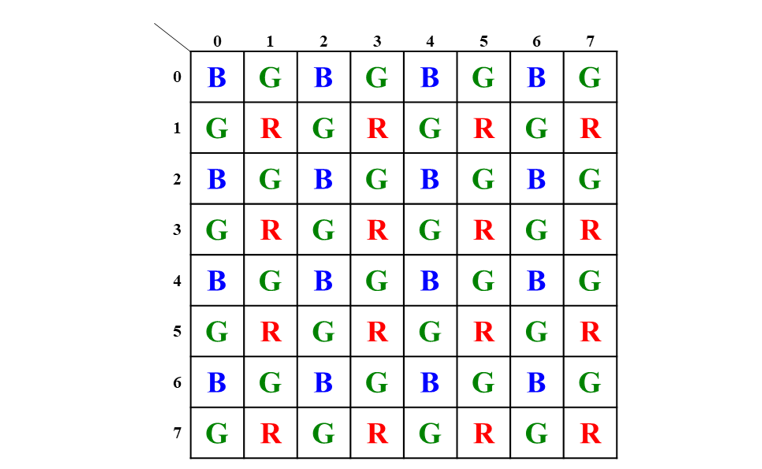
Figure 3 : Mosaic images of Pixel Identification with Bayer CFA
The characteristic feature of the colour demosaicking approach necessitates a larger area on the chip for its VLSI implementation. It's apparent that this approach eschews divisors and multipliers, yet it notably enhances shifter operations, as well as additions and subtractions. Hence, the proposed method will primarily concentrate on area reduction.
This reduction in area is achieved by employing arithmetic operations within a colour demosaicking algorithm, resulting in a diminished number of garbage signals, logic gates, memory logic elements, and power consumption. In this specific scenario, the presented colour demosaicking architecture comprises three distinct hardware sharing units for mathematical operations: additions, shifts, and subtractions, respectively.
Consequently, the planned approach advocates for the use of carry-skip adders instead of the more traditional complete adders to attain higher speeds and efficiencies in the addition process. In the proposed work, a digital image filtering technique for colour demosaicking utilizing carry-skip adders is designed. The intended outcome is to reduce the quantity of logic gates in FPGAs, thereby potentially decreasing their space, latency, and power requirements.
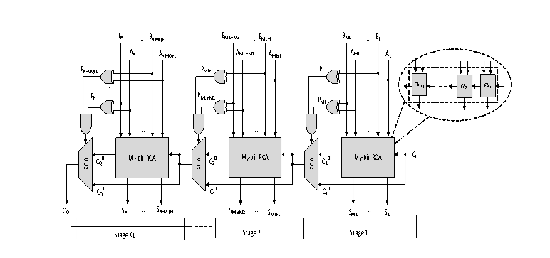
Figure 4 : The CSkA Architecture
Figure 4 depicts the architectural design of the Carry-skip adder for the structure. This adder has an N-bit size, and it is built on RCA blocks. These blocks have a chain of complete adders, and the speed and delay operations of this architecture are based on multiplexers. It does this by lowering the total amount of critical route delays in the design while simultaneously raising the operating speed of traditional carry skip adders with huge sizes. Further operations of an XOR gate structure coupled with an AND gate structure will provide a multiplexer selection choice. This option is dependent on the logic of the input and carry.
It corresponds with A1 to AN and B1 to BN, and the output created is S1 to SN in this RCA block, which has a chain of typical cascaded full adders, and the inputs A and B belong to the size of multi-bit capability. In this operation, after the A and B inputs have been provided, they will be added in the RCA block, and the EXOR gate operations will provide a selection signal according to the equation (1).

Where Pi represents the propagation signal that is formed from Ai XOR Bi, and each of the Pi....n bit is ANDed together to create what is ultimately the supplied input of the multiplexer selection process. This multiplexer will make its decision on whether to do a skip operation based on the carry generation from C001 to C0Q.
Bi-Cubic Interpolation Process
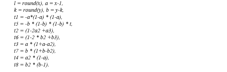
The area around 16 pixels must be used for bi-cubic interpolation [1], and there must be 16 floating-point operations performed. This method is comparable to window processing. Because of this, approaches of temporal and spatial parallelism may be employed for its implementation, which qualifies the Bi-Cubic interpolation technique as a possibility for being implemented utilizing FPGA technology. Figure 5 illustrates the bi-cubic interpolation neighborhood, and equation 1 provides a description of it. A to P represent the image pixels, covered by the 4 by 4 mask, t1, t2, t3, and t4 represent the vertical coefficients; t5, t6, t7, and t8 represent the horizontal coefficients; and x and y represent the pixel coordinates that will be interpolated. The Equation (2) gives the detailed understanding of the above description.
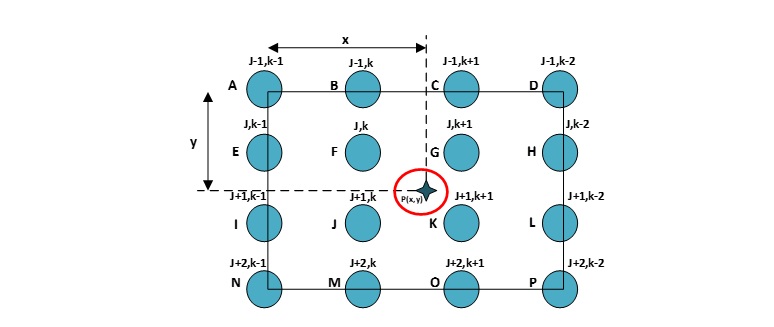
Figure 5 : Neighborhood Interpolation using a Bi-Cubic function.
The objective is to deduce the value of P(x,y) using the neighboring 4x4 pixels as a reference point.
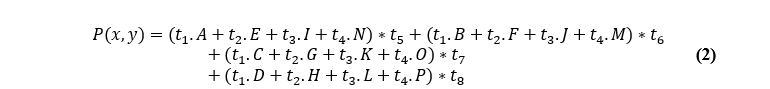
Where
The step-like boundary issue that is present in closest neighborhood interpolation is not present in bi-cubic interpolation, and it is also capable of coping with the blurring that occurs with linear interpolation. In bitmap displays, the bi-cubic interpolation method is often used in order to allow image zooming in reference to an arbitrary point. If nearest-neighborhood approaches were utilized, there would be an increase in the number of places with the same brightness. Bi-cubic interpolation does an excellent job at preserving the small details in an image.
3. PROPOSED SRD-CFA BI-CUBIC INTERPOLATION
The single image SR approach should be used in order to get a higher resolution while using just a single image LR as an input. The reconstruction step of Bayer Bi-Cubic CFA is simple and has the ability to generate a high-speed processing method than multiple image SR. This is because the reconstruction stage is uncomplicated. The present investigation aims to devise a super resolution demosaicking (SRD) methodology that can effectively reconstruct a high-resolution full-color image from the su-sampled image, while being robust and not reliant on a training process. The research aims to accomplish this by developing a technique that is called super resolution demosaicking (SRD). The acquisition model functions under the presumption that the observations are degraded. It does this by making use of blur and noise that has been determined in advance. In the method of reconstruction, unknown registration parameters and the demosaicking are concurrently estimated through a process of iterative estimation. The execution of qualitative and quantitative tests on synthetic observations is the method that is used to identify images with high performance levels.
In order to improve the PSNR and SSIM, it is necessary to develop the Fully Pipelined Super Resolution Color Demosaicking approach that utilizing the Bi-Cubic interpolation method as shown in Figure 6. The present study outlines a proposed methodology for the development of an SR-Demosaicking Hardware machine utilizing a Carry Skip adder. The performance of the hardware machine will be evaluated through conventional methods. Consequently, the tests conducted and presented in this study evaluate the performance of the SRD algorithm and compare its results with those of the proposed Bi-Cubic interpolation.
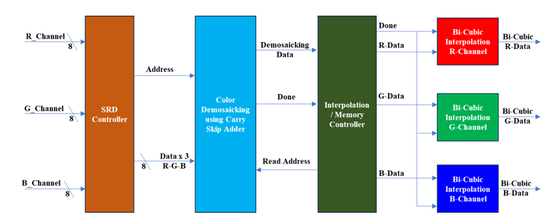
Figure 6: Proposed Architecture of SRD-CFA-Bi-Cubic Interpolation
The proposed approach of super resolution demosaicking color filter arrays utilizing the Bi-Cubic interpolation technique is shown in Figure 6. This preliminary design begins with the SRD controller; it takes its input from a total of three different memories, including Red Channel memory, Green Channel memory, and Blue Channel memory. This RGB input will make available the Demosaicking hardware machine, and as a result, the SRD controller will combine the RGB data such that it is presented in the format in sequence of “R", "G", and "B" is observed. Following that, the demosaicking will accept the input data, store it in the internal memory, and then process the three distinct hardware sharing machines in accordance with the design presented in Figure 6. When demosaicking has completed the operation, it will send an acknowledgement signal to the Interpolation memory controller indicating that it is finished. This Interpolation memory controller obtains the data from the demosaicking CFA and provides it to the Bi-Cubic interpolation in the distinct formats of the R-Channel, G-Channel, and B-Channel respectively. Figure 6 illustrates the internal architecture of the Bi-Cubic interpolation method.
In the first iteration, the architecture as shown in Figure 7, reads the input buffer memory, rows of images, and begins processing using from demosaicking interpolation. When one row of the image has been processed by the architecture, the output is the same as with Horizontal Interpolation. After processing, the generated image row is saved to the shared storage. Starting with the second iteration and continuing until the final iteration, the architecture simply receives one column from the image and begins processing in a manner similar to the Vertical Interpolation method; the generated image row is then stored in output memory.
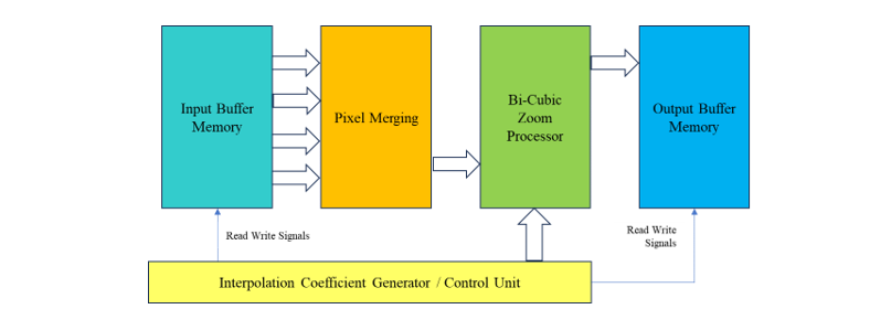
Figure 7 : Hardware architecture of Bi-Cubic Interpolation
Each processor receives a control signal from the Interpolation Coefficient Generator / Control unit that tells it when to begin processing and where to store the output. The primary parts of the proposed architecture are seen in Fig. 6. First, the input buffer memory; second, the output buffer memory; third, the Bi-Cubic interpolation processor; fourth, the CU (Control Unit) or interpolation coefficient generator. The results of bi-cubic interpolation are included among the best of the available interpolation methods, and the method itself is rather robust. The implementation of other methods, which are simpler and take up fewer FPGA resources, is more viable in sequential processors. Other, less sophisticated interpolation methods are quicker than Bi-Cubic Interpolation yet implementing them on an FPGA doesn't provide a noticeable speedup over using a regular CPU.
4. RESULTS AND DISCUSSION
Interpolation is generally used as a starting point in demosaicking methods, with further adjustments made to the resulting approximation. It is possible to replace the interpolation step in these techniques with the proposed approach, and the resulting picture will also benefit from SR. This study presents tests that do just that, comparing the SRD algorithm's performance against that of interpolation. The lower resolution of the input image was added to 256x256 image resolutions in this effort. At this stage of the simulation process, the input picture is fed into the MATLAB GUI for Image to Hex Conversion and Hex to Image Conversion, with the SSIM and PSNR values also being calculated. The results of the simulation of the super resolution demosaicking color filter array is given in Figure 8.

Figure 8 : Simulation Results of Super Resolution Demosaicking - CFA
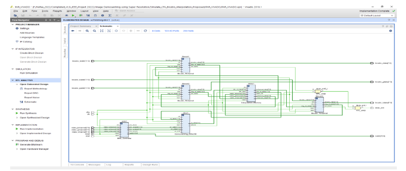
Figure 9 : RTL Schematic oof Super Resolution Demosaicking
It was simulated via Questa Sim, and the MATLAB results output shown in Figure 10, which exhibits Kodim_15 from the Kodak dataset. This requires 36.543 PSNR, 0.96187 SSIM, and 14.4138 MSE. Typical Akiyo image news presenter is shown in Figure 10, along with its 38.6767 PSNR, 0.97797 SSIM, and 8.8189 MSE values. Figure 12 displays the kodim23 that was derived from the Kodak datasets; it has a PSNR of 37.831, an SSIM of 0.97785, and MSE of 10.7147. All of these experiments indicate that SRD CFA, it was developed using VHDL and synthesized using Xilinx Vivado ZYNQ-7 ZC702 FPGA, with two comparisons of Ripple carry adder using SRD CFA, and Carry skip adder using SRD CFA, Table.1 displays the comparisons analysis table with compared LUT, LUTRAM, FF, IO, BUFG, Dynamic Power, and Static Power.
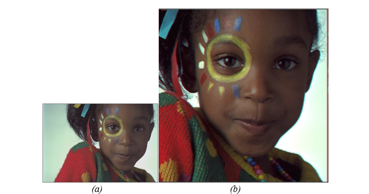
Figure 10 : Kodim15 from Kodak datasets (a) input image of demosaicking interpolation at 256x256 image resolutions, (b) output image of demosaicking with Bi-cubic interpolation at 512x512 image resolutions its contain 36.543 PSNR, SSIM=0.96187, MSE = 14.4138.
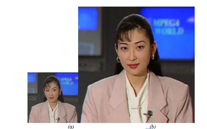
Figure 11 : Akiyo image, (a) input image of demosaicking interpolation at 256x256 image resolution. (b) output image of demosaicking with Bi-cubic interpolation at 512x512 image resolutions it contain 38.6767 PSNR, SSIM=0.97797, MSE = 8.8189.
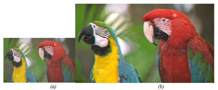
Figure 12 : kodim23 from Kodak datasets (a) input image of demosaicking interpolation at 256x256 image resolutions, (b) output image of demosaicking with Bi-cubic interpolation at 512x512 image resolutions its contain 37.831 PSNR, SSIM=0.97785, MSE = 10.7147.
Table 1 : Comparisons of Image Demosaicking and Bi-Cubit Interpolation using Super Resolution with Conventional RCA and Carry Skip Adder
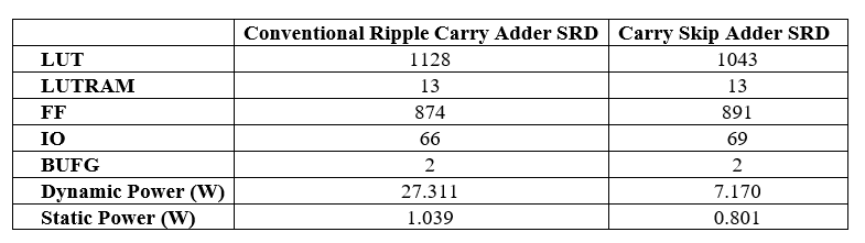
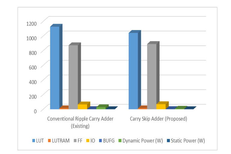
Figure 13 : Contrastive Study Super-resolution image demosaicking with Bi-Cubic interpolation chart
5. FUTURE WORK
In this work, An Efficient VLSI Architecture for Bi-Cubic Interpolation using Carry Skip Adder is proposed and implemented. A super-resolution demosaicking (SRD) technique is implemented to reconstruct high-resolution image through hardware-oriented colour demosaicking methods. This VLSI architecture is implemented using VHDL, and MATLAB used for image display. The results are tabulated as PSNR and SSIM values and analysed. ZYNQ-7-ZC702 FPGA (Xilinx) at the speed of 200MHz is used for the synthesis. The results proved the substantial saving of memory with lesser number of calculations without reducing the performance, while maintaining the original performance during implementation. The results proved that Carry Skip Adder SRD based demosaicking algorithm found to be out performed the Conventional Ripple Carry Adder SRD. As future work, to improve the power and energy consumptions image demosaicing hardware can be designed and implemented so that it is more suitable to the real time applications.
REFERENCES
Wael Saafin, Abdelbasset Brahim, “Image Demosaicking using Super Resolution Techniques”, Proc. of the International Conference on Electrical, Computer and Energy Technologies (ICECET 2022), 20-22 July 2022, Prague-Czech Republic, 2022 IEEE.
Shih-Lun Chen, Huan-Rui Chang, “Fully Pipelined Low Cost and HighQuality Color Demosaicking VLSI Design for Real Time Video Application”, 2015, IEEE Transactions on Circuit and System-II: Express Briefs;
Ming-Che Yang, Kuan-Ling Liu, and Shao-Yi Chien, “A Real-Time FHD Learning Based Super Resolution System Without a Frame Buffer”, IEEE Transactions on Circuit and System-II: Express Briefs, Vol. 64, No.12, December 2017.
Kulwinder kaur, Inderpreet Kaur, Jaspreet Kaur, “Survey on Image Interpolation”, Volume 6, Issue 5, May 2016, International Journal of Advance Research in Computer Science and Software Engineering.
Prachi R Rajarapollu, Vijay R Mankar, “Bicubic Interpolation Algorithm Implementation for Image Appearance Enhancement”, International Journal of Computer Science and Technology, June 2017.
Auangkum Rangsikunpum, Ekachai Leelarasmee, Suree Pumrin, “A Design of Sign Video Image Expander for HDMI Source using Bicubic Interpolation”, 2017, 14th International Conference on Electrical Engineering/Electronics, Computer, Telecommunications and Information Technology (ECTI-CON).
K. Sudha Rani, W. Jino Hans, “FPGA Implementation of Bilinear Interpolation Algorithm for CFA Demosaicking”, International conference on Communication and Signal Processing, April 3-5, 2013, India.
Nguyen Viet Hung, Nguyen Thi Thu Hien, Phan Thanh Vinh, Nguyen Thi Thao, Nguyen Tien Dzung, “An Utilization of Edge Detection in a Modified Bicubic Interpolation Used for Frame Enhancement in a Camera-based Traffic Monitoring”, KICS-IEEE International Conference on Information and Communications with Samsung LTE & 5G Special Workshop, 2017, IEEE.
Yunshan Zhang, Yuhui Li, Jie Zhen, Jionghao Li, Ran Xie, “The Hardware Realization of the Bicubic Interpolation Enlargement Algorithm Based on FPGA”, 2010 IEEE, Third International Symposium on Information Processing.
Marco Aurelio Nuno-Maganda, Miguel O. Arias-Estrada, “Real Time FPGA-Based Architecture for Bicubic Interpolation: An Application for Digital Image Scaling”, 2005, IEEE.
Jianmin Li, Xiangjian He, “Bi-cubic Interpolation for Image Conversion from Virtual Hexagonal to Square Structure”, 2008, DBLP, Computer Science Bibliography.
Mehran Motmaen, Majid Mohrekesh, Mojtaba Akbari, Nader Karimi, Shadrokh Samavi, “Image impainting by hyperbolic selection of pixels for two dimensional bicubic interpolations”, 2018, IEEE, Electrical Engineering (ICEE).