
Current Issue
Shaping Radiation with Line Source Antenna for Ramp Pattern Generation
Ravindranath. J.
Department of Electronics and Communication Engineering, R.V.R & J.C. College of Engineering, Chowdavaram, Guntur-522019, A.P, India.
ABSTRACTArray antennas are essential in communication technology because they can produce focused beams of electromagnetic radiation that can be precisely shaped and directed for various applications. These antennas typically generate a radiation pattern with a primary lobe, the main beam, accompanied by smaller minor lobes. The size and distribution of these lobes depend on the array's design and configuration. For large array antennas, the main beam becomes extremely narrow, enabling precise point-to-point communication over long distances. This precision is especially beneficial for applications requiring accurate targeting or transmission to specific locations. However, achieving such optimized performance requires careful design and engineering. This study, builds on Woodward's amplitude control method, initially developed for generating sector beams, to create ramp patterns with unique applications in antenna engineering. By adjusting the amplitudes of the signals fed into each element of the array, the researchers can shape the resulting radiation pattern to meet specific requirements. The paper provides detailed analysis and computational data demonstrating the effectiveness of this approach in achieving the desired beam patterns. These results offer valuable insights into antenna design and optimization, potentially advancements in wireless communication, radar systems, and satellite communication.
Keywords:Array Antennas, Communication, radiation pattern, lobes, Beam, performance, Ramp patterns, computational data, Wireless Communication.
1. INTRODUCTION
The line source antenna is characterized by its lengthy, narrow, and straight design. In this type of antenna, the directional properties are determined by variations in the field or current strength along its longitudinal axis. These variations are continuous, distinguishing line source antennas from discrete element arrays, although large arrays can sometimes be treated as continuous distributions for analytical purposes.
Here are the key points about the line source antenna:
- Design and Structure: It has a continuous structure where the currents or fields vary along its length, making it a line source rather than a collection of discrete elements.
- Pattern Composition: Below are the primary components of the radiation pattern generated by a line source antenna.:
- Element Factor: This factor is contingent upon the type and orientation of fields or currents within a typical segment of the source. Generally, it displays minimal directivity, particularly in directions that might otherwise enhance the directivity of the spatial factor.
- Space/ spatial Factor: This is the highly directional component of the radiation pattern, determined by the relative variations in field or current strength along the source. The space factor's shape is crucial and is the primary focus of the antenna designer.
- Design Objective: The primary objective when designing the spatial factor is to achieve the finest beamwidth and lowest side lobes feasible within the available aperture, without pursuing super-gain. This approach helps mitigate practical issues, such as heightened sensitivity to minor changes in design or environmental conditions.
In summary, the line source antenna's performance is predominantly determined by the careful design of the space factor, while the element factor plays a less significant role in enhancing directivity. The aim is to optimize the space factor to achieve the desired radiation pattern characteristics.
Array antennas are preferred as they provide flexibility in design, outstanding gain and high directivity. The array antennas are designed to produce radiation pattern which consists of nulls in particular directions and to produce narrow beams in the desired directions. A collection of beam shapes [1-7] are generated by these array antennas and are effective in numerous applications. Standard beam shapes are narrow/pencil, sector, cosecant, ramp, and stair-step etc. The narrow beams [8,9] are widely used for point-to-point communications including high resolution radars. Ramp patterns [10-18] have the applications to those of pencil beams. It is possible to generate enhanced/optimized beams from well-engineered array antennas. Optimization is achieved by using amplitude [7], spatial [8], and phase [9] distributions or their combinations. In the current research work, an amplitude distribution function is designed by using Woodward technique for the creation of ramp patterns.
2. SYNTHESIS OF AMPLITUDE DISTRIBUTION FOR DESIRED RADIATION BEAM SHAPES
The radiation pattern exhibited by a line source with a length of 1 can be described as follows
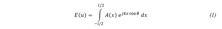
if A(x) is represented by Fourier series

then radiation pattern is given by

&

where u=k cosθ
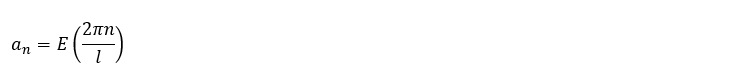
It is obvious from the above expression; the design problem is reduced to the determination of the constant an which results any given pattern over a given region. The coefficients an are chosen such that the approximate pattern EN(k cos θ) at the points given by

The coefficient an are now obtained from
if an is changed

then amplitude distribution

Positive Ramp pattern is defined by

where u0= 0.4
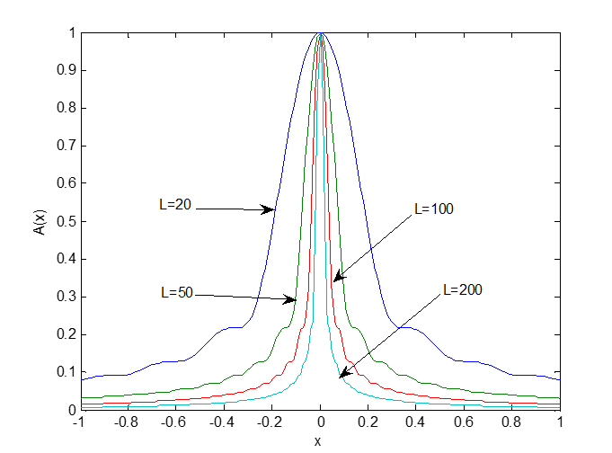
Figure 1: Amplitude Distribution function for Ramp pattern.
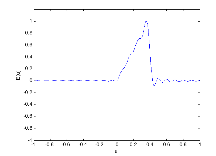
Figure 2: Normalized Radiation Ramp pattern ( 2 L / λ = 20 )
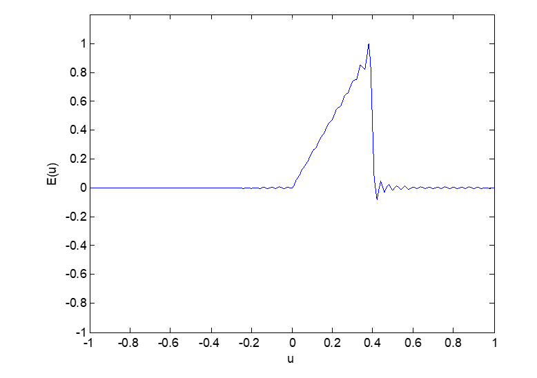
Figure 2: Normalized Radiation Ramp pattern ( 2 L / λ = 50 )
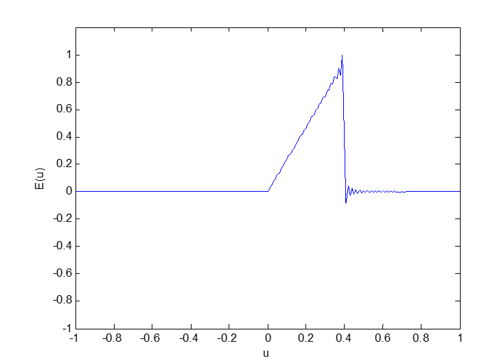
Figure 2: Normalized Radiation Ramp pattern ( 2 L / λ = 100 )

Figure 2: Normalized Radiation Ramp pattern ( 2 L / λ = 200 )
3. RESULTS AND CONCLUSIONS
This study demonstrates the feasibility of using line source antenna with amplitude control to generate ramp patterns. The amplitude distribution functions for generating ramp patterns have been thoroughly evaluated and are now presented in Figure 1. The resultant radiation patterns are presented in Figures (2-5). The patterns presented in the present work are to be very close to the desired patterns when the array consists of a large number of elements. The provision of independent adjustment of the coefficients near a discontinuity is especially valuable.
ACKNOWLEDGEMENTS
Author expresses his deep sense of gratitude and indebtedness to my beloved Prof. Late A. Sudhakar and the Management of RVR&JC college of Engineering Guntur for their support for this work.
REFERENCES
- M.T. Ma, Theory and applications of antenna arrays, John Wiley and Sons, NY,1974.
- D. Steinberg, Principles of aperture and array system design, John Wiley and Sons, NY,1976.
- Elliot, R. S., “Design of line source antennas for narrow beam width and asymmetric low side lobes,” IEEE trans., vol. AP – 23, pp.100-107, 1975.
- C.L. Dolph, “A current distribution for broad side arrays which optimizes the relationship between beam width and side lobe level”, proc. IRE, vol. 34, pp.335- 348, 1946.
- R.F. Harington, “Side lobe reduction by non-uniform element spacing” IRE Trans. on A & P, pp.187, March 1981
- P.M. Wood ward and J. D. Lawson, “The theoretical precision with which an arbitrary radiation pattern may be obtained from a source of finite size”, J. IEE, vol.95, pt .3, no .37, pp. 363-370, Sept. 1948.
- M.I. Skolink (ed), Radar Handbook, Mc Graw Hill, NY, 1970.
- H.G. Booker and P.C. Clemmow, “The concept of an angular spectrum of plane waves, and its relation to that of polar diagram and aperture distribution “Proc. IEE (London), paper no.922, Radio Section vol. 97, pt. III, pp.11-17, Jan. 1950.
- S.A. Schelkunoff, “A mathematical theory of linear arrays”, Bell system technical Journal, vol.22, pp.80 – 107, 1943.
- P.M. Woodward, “A method for calculating the field over a plane aperture required to produce a given polar diagram”, J.IEE, vol. 93, pt. IIIA, pp .1554- 1558, 1946.
- Ajoy Chakraborthy, B.N. Das, “Scanning of sector and cosecant beams generated by a circular aperture”, IEEE trans. On Antennas and Propagation, vol. AP – 32, no-9, Sept.1984.
- T.T. Taylor, “Design of line source antennas for narrow beam width and low side lobes”, IRE trans, Antennas & Propagation, vol. AP – 3, no. 1, pp 16-28 , Jan 1955.
- T.T. Taylor, “One parameter family of line sources producing modified sin (u)/u pattern, “Huges aircraft co. tech. Mem. 324, culver city, Calif Contract AF 19(604) – 262 – F – 14, Sept. 4, 1953.
- R.F. Hyneman, R.M. Johnson, “A technique for the synthesis of shaped beam radiation pattern with approximately equal – percentage ripple, “IEEE trans. On Antennas &propagation vol. AP- 15,no. 6 pp. 736-743, Nov. 1967.
- K. R. Gottumukkala, G.S.N. Raju, “An useful aperture excitation function for the generation of narrow beams,” IEEMA Journal, June 1987.
- G.S.N. Raju, P.M. Rao, K.R Gottumukkala, Ajoy Chakraborty, “Investigations on arrays of non – identical radiators, “Microwave and optical Technology Letters, Vol. 5, no.1, pp.26-31, Jan 1992.
- G.S.N. Raju, Ch. L. Kantam, S.R. Sekhar, K. Satish, K.M. Prasad, K.R. Gottumukkala,” Side lobe control using non- linear phase distribution, “Proc. of APMC 90, Japan.
- G.S.N. Raju, K.R. Gottumukkala, Murali, K. Gokaraju”, Square top patterns from arbitrary source positions”, Proc. of ICCS, Singapore, 1990.